1 Summary
本文介绍屏幕空间反射中最重要的一步——基于 hierarchy depth buffer(HZB) 的 ray march算法,主要参考了 [1] 中的实现。
ray march算法的目的是为了根据屏幕空间深度得到光线在屏幕上的交点,相比于世界空间的光追,这是一种开销很低但仅局限于屏幕空间的做法,也就是若光线交于相机看不到的表面,那么屏幕空间ray march则无法得到求交结果。而 hierarchy depth buffer 则提供了四叉树的加速结构,每一级mipmap都取上一级四个深度中的closest depth。假如光线在 closest depth 的表面之上(距相机更近),那么可以光线也不会与更精细层级相交,因此可以快速行进不会相交的区域。
2 hierarchy depth buffer
hierarchy depth buffer(HZB) 是构建depth buffer的mipmap形式,但与API接口提供的mipmap构建方式(取均值)不同,hierarchy ray march需要每一层级取前一层级四个深度中的closest depth,具体取最小或最大由depth实现决定。本文采用 \([0,1]\) 的depth,越大距相机越远,因此取最小深度。
3 Construct Ray
对于屏幕空间,往往已知光线起点像素坐标
fragCoord,以及基于需要采样的光线方向 rayDir
(位于世界/相机空间,本文采样相机空间)。ray march
过程在屏幕空间进行,同时为了方便在不同mip层级行进,需要得到screen uv
space(即 \([0,1]\times [0,1]\times
[0,1]\))下的光线起点,以及屏幕空间的光线方向。
(fragCoord, depth) 变换到view space得到
viewRayPos,沿光线方向行进一个单位得到
nextRayPos = viewRayPos + rayDir,最后将二者都变换到screen
uv space,得到 origin 与
nextRayScreenPos,光线方向
direction = nextRayScreenPos - origin,注意不需要normalize,因为这并不是三维空间的方向。
4 Ray March
给定光线起点 origin 与光线方向
direction,都位于 screen uv
space。在光线行进过程中,会反复执行一下步骤:
先行进 linear step,即在当前层级行进一个像素。执行基于深度的求交判断,有:
如果光线从当前像素在表面上(更靠近相机)掠过,表示无交点,那么去更高层级(表示更大步长)。
如果光线与当前像素相交,表示可能相交,那么去更低层级(表示更小步长)
4.1 Linear March
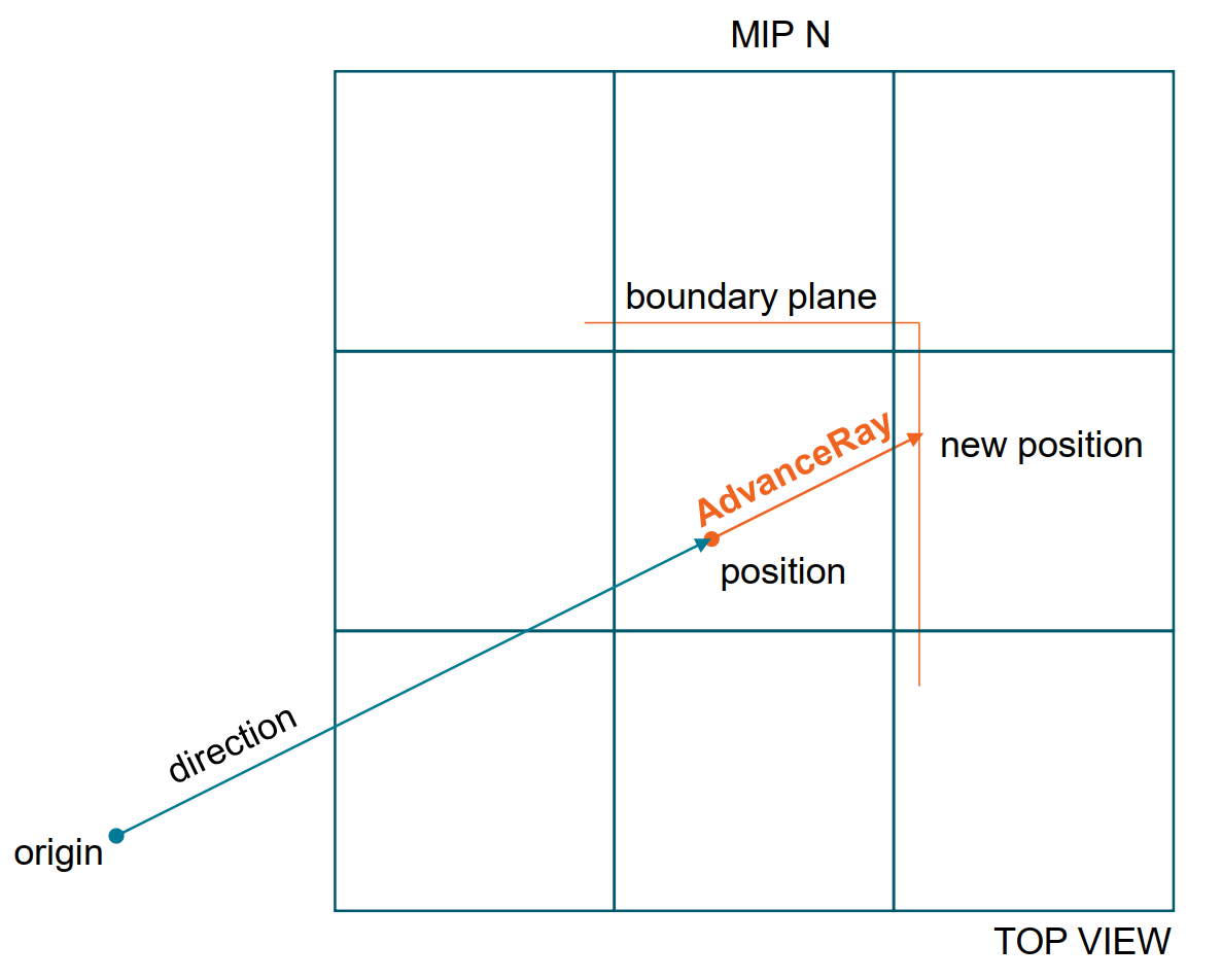
行进一个步长是希望沿着光线方向行进到下一个像素,同时下个像素内执行一个偏移,如图 Fig-1 所示。
行进步长 marchStep 可设置为
1 | vec2 marchStep = mix(vec2(0.0), vec2(1.0), greaterThanEqual(direction.xy, vec2(0.0))); |
像素内部偏移量 uvOffset 以像素大小为单位,可设置为
1 | vec2 uvOffset = 0.005 * exp2(baseLevel) * (1.0 / screenResolution); // baseLevel 表示 ray march 执行的最低层级 |
假设当前光线位置 currentRayCoord 以及当前层级分辨率
currentMipResolution,linear march的执行如下
1 | vec2 LinearMarch(vec2 currentRayCoord, vec2 currentMipResolutionInv) // currentMipResolutionInv 为倒数 |
在进行求交之前,光线需要先行进一步,避免与自身所在像素自相交,行进到下一个像素的boundary plane处,有
1 | void InitRay(vec3 origin, vec3 direction, vec3 directionInv, vec2 currentRayCoord, |
4.2 Intersection
每次迭代都需要进行判断是否与将要行进到的像素有交点,以此来决定下一步应该如何执行。如何判断光线与将要行进像素是否相交?
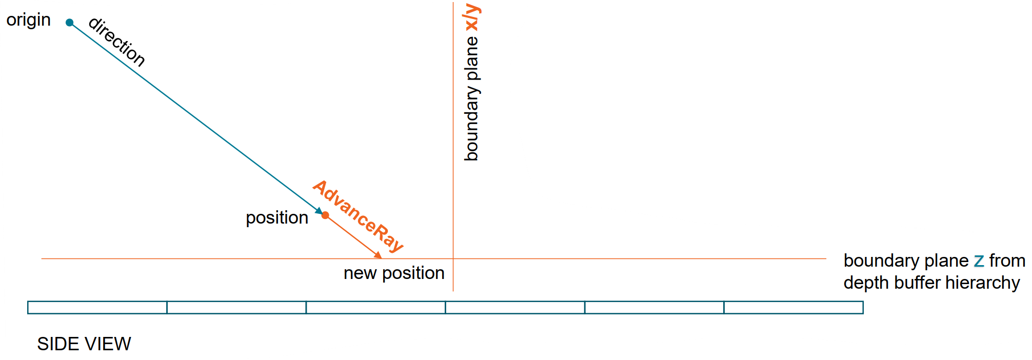
假设光线当前位置为 positton,将要行进位置为 new position,如图 Fig-1 所示。new position 处的 (x, y, surfaceZ) (surfaceZ为该处像素的深度) 形成了一个bounding box的一半,即相邻的三个面组成的boundary,可以看到 Fig-1 中,俯视近平面所展示的 x/y plane 形成的黄色 boundary plane。从侧面看近平面如图 Fig-2 所示,相机位于上方,两条黄色 boundary line交点处即为 new position。
对于一个像素而言,其内部深度都是相同的,光线是否会与即将行进的像素相交,通过查看两个端点 position与new position即可:
- 光线当前位置 position 与表面的关系有:position.z < surfaceZ,光线在表面之上;否则,光线在表面之下,可能与像素相交
- 求光线与new position形成的boundary plane (x, y, surfaceZ)的最近交点,如果没有与z plane相交,则表示光线可以从new position上方掠过
因此,对于光线当前位置 position 的两种情况而言:
- position.z <
surfaceZ:光线在表面之上,不会与position所在像素相交。
- 光线与 z plane 相交,表示光线与下一个像素相交
- 否则,即与 x/y plane 相交,表示光线与下一个像素也不相交
- 否则,光线在表面之下,与position所在像素相交
为了能够使用 hierarchy depth buffer 加快速度,应该有:
- 如果本次迭代的行进有可能相交,则去更细粒度层级,即使用更小行进步长。例如上述情况 a,光线可以行进到 z plane 交点位置;c,光线位置不变,等待更细粒度层级测试
- 如果不会相交,则去更粗粒度层级,即使用更大行进步长。例如上述情况 b,光线可以行进到 x/y plane 的交点位置。
上述迭代一直进行到没有更细粒度层级可用时,表示已找到可能交点;否则,达到迭代次数上限后,表示无法找到交点。
1 | // surfaceZ: depth at currentRayCoord.xy |
每次迭代后,调整层级
1 | bool skipTile = AdvanceRay(...); |
4.2.1 特殊情况 :confused: :question:
上面描述都是以光线方向背离相机为例,当光线方向朝向相机时,需要特殊注意:
- position.z >= surfaceZ:与前述过程没有不同
- position.z < surfaceZ:此时不能使用 z plane 的交点,因为得到的
4.2.2 线性查找
前面讲到,迭代到没有更细粒度层级时,表示找到交点,退出迭代。但如果是超出最大层级时呢?一种做法是,可以看作无法找到交点,但如果想要查找更充分,此时可以降为在最大层级线性查找过程,迭代后层级调整实现修改如下
1 | bool skipTile = AdvanceRay(...); |
4.2.3 交点是否有效
前述讲的求交测试都是基于深度信息进行的,如果光线走到了像素背后,则表示相交。但实际上,像素占据了表面一定面积,而该小部分表面并非与近平面平行或者并非是平坦的,因此所在表面存在一定厚度,有可能光线从表面背后穿过去,只有在像素厚度范围内的光线,才算是相交。因此,在得到交点后,还需要进行验证是否有效。
提取交点 position 处的深度值
surfaceZ,分别将
position.z与surfaceZ
变换到线性空间(相机/世界空间),得到 rayDepth 与
hitDepth,有
1 | bool TestThickness(float rayZ, float hitZ) |
4.3 Put All Together
1 | vec3 HierarchyRayMarch(vec3 origin, vec3 direction, int maxIteration, |
5 Reflection
最后简要介绍下屏幕空间反射的反射部分。屏幕空间反射希望得到金属材质的着色点的反射信息,首先需要在着色点处根据材质信息,重要性采样得到反射光线的方向。以着色点为起点、反射光线的方向组成的光线,在屏幕空间执行ray march,找到的交点即为反射点。接下来,SSR直接将上一帧反射点的颜色(不包含反射)作为反射点向着色点发出的radiance。注意:这是一种简单的近似,并非PBR过程,因为屏幕上的颜色实际上应该是屏幕像素向相机发出的radiance,这里直接近似作为其向着色点的radiance。
Reference
[1] https://github.com/GPUOpen-Effects/FidelityFX-SSSR